Introduction #
I probably heard about FreeCAD first in the early 2010s, and downloaded it around the same time (likely around version 0.11). At that time, I was unable to get anything working and continuously had to fight with the UI to get out of modes I didn’t understand. With the release of 1.0 in November of 2024, it was rumored that FreeCAD had fixed their UI enough to make it workable so I decided to give it another go.
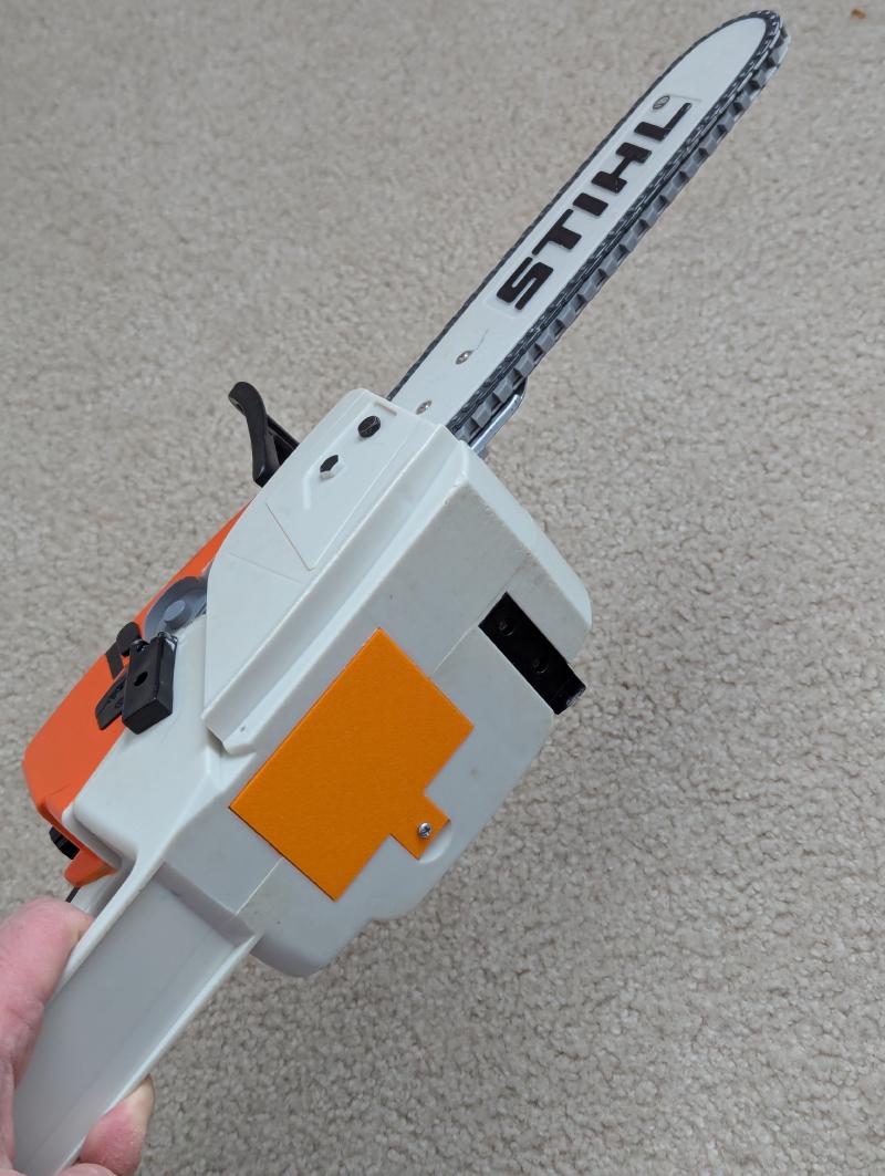
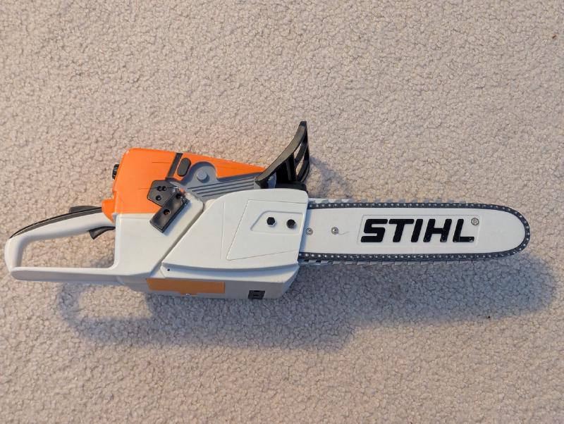
For this first project, I targeted a simple battery cover for a kid’s Stihl Chainsaw toy that we received second hand. It was gifted to us with a cut out piece of metal to keep the batteries retained, but my children had bent that badly out of shape and a new cover was needed.
The Model #
Initial Measurements #
Taking my trusty pair of calipers (something like this) I took some initial measurements of the battery compartment opening.
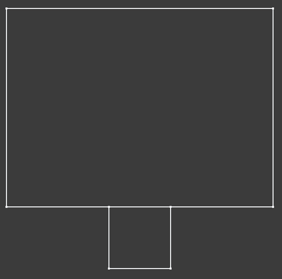
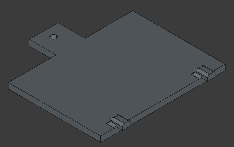
45mm x 60.74 for main body
Tabs for locking in place are 4.83 - 4.93mm wide, make them extend 5mm, can be up to 3.5mm thick
--Put them 7.15mm in from edges, 4.5 wide
Screw tab for 4.15mm diameter head screw, at least 2.61mm diameter thread portion.
--Inset 4.8mm from edge. Tab is 14.1mm wide, 13.2mm deep, no more than 2.98 thick
Using these notes I started with a first revision. Unfortunately, this revision uncovered a few problems with my notes:
-
The thickness of the location tabs was way too thick - pushed on the AA batteries (revised down to 2mm)
-
Screw diameter had to be 3mm diameter to fit screw snugly
-
Small tweaks made to thicknesses, tab locations, etc.
The FreeCAD Process & Fusion360 Corollaries #
I don’t want to make this post an entire step by step tutorial on using FreeCAD, but I do want to take a few notes on the process in the hopes that it will help other Fusion 360 users adapt to the quirks of FreeCAD. Starting from the beginning, booting into FreeCAD gives you a window like this.

After you go to File -> New, you will get a new tab along the bottom that says “Unnamed : 1” to the right of the Start screen. On the left there is a window called “Tasks” that walks you through the traditional design work flow: create body -> create sketch. Once you are working on a sketch is where I started to experience my first “gotchas” with the FreeCAD process.
In Fusion, I am used to extruding subsets of a sketch by shift-clicking different enclosed areas. This does not seem to work in FreeCAD, and the entire outline of your sketch gets extruded instead. It is possible that a nested element can be detected (according to Grok), but since I did my sketch as two separate rectangles with a nested circle, the tool couldn’t know which areas were to be extruded and which weren’t. It might be possible to fix this with a polyline, but in my case I just separated the circle to a different sketch.
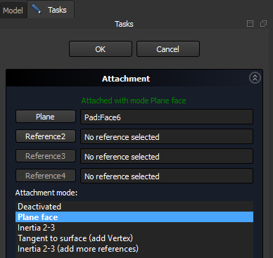
After drawing the outline, the next struggle was with creating a new sketch on the face of the newly “padded” body. When clicking to create a sketch, the default options are the three planes along the axes. To create a sketch on the surface of a body, you have to “attach” it. After creating a sketch on one of the planes, you can right click on it in the model window (left side of the screen) and go to the attachment editor. Here you can change the attached plane from one of the 3 coordinate planes to a face of the body you are working on.
With these things in mind, the rest of the battery cover can be completed.
FreeCAD Learning Resources #
In completing this project, I relied on Grok to search for the recommended process but since Grok is text based it is hard to follow exactly. While looking online for help, the absolute best resource I found for learning FreeCAD is the MangoJelly Solutions Channel on YouTube.
Conclusion #
In the end it was my 3rd revision that finally had a good enough fit to the toy. I printed the model in an orange color that I had left over from Halloween that doesn’t quite match the Stihl orange, but looks close enough. If you need the model to print your own, or as a reference for a similar design, it can be found on Maker World.